
CNC Grooving Guide – Know the Every Unknown
Like CNC knurling, CNC grooving is a crucial modern machining method. Just as utilizing knowledge of knurling techniques can be applied to better results, In the same way, acquiring an understanding of grooving techniques brings with it a greater measure of accuracy, fitting and function. This guide will take you through the whole process including tools and methods, key considerations and more. By the end you’ll be able to select the right lathe grooving tool and escape the most common pitfalls in machining.
What Is CNC Grooving?
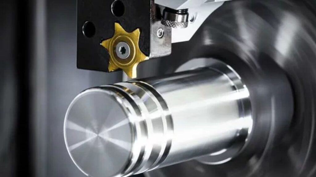
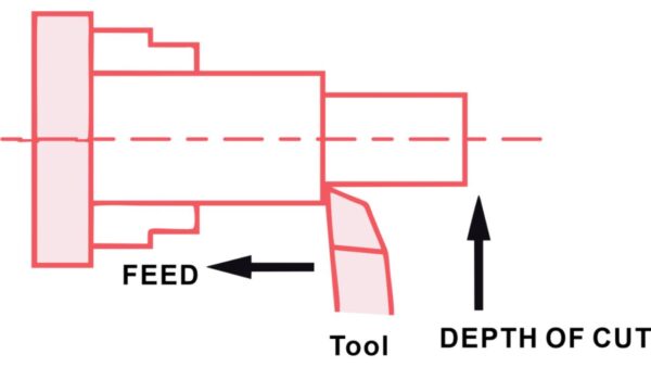
CNC grooving, also known as recessing, is a narrow channel cut into a workpiece using lathes or turning centers. You will use it most often for seals, O-rings, or snap rings in assemblies. The width, depth and location of the groove has to match design specs. Grooving is different from parting or threading, as it targets specific recesses necessary for mechanical fit In groove machining, even small deviations affect part function. Deep and metal grooving techniques give superior control for accuracy.
Types of CNC Grooving Tools
The right tool is also very critical when it comes to CNC grooving. The type of tool you use determines the performance, precision and durability of your grooves. Here are the main types of CNC grooving tools explained in complete detail to assist you in choosing the perfect tool for your needs.
Material Composition
The first step is to know what material your tool is made of. It directly affects its strength, wear resistance, and cost.
- Cemented Carbide Tools: Excellent hardness for grooving metal operations. They perform well in high-speed or heavy cutting. For long production runs, carbide gives consistency and life using a lathe grooving tool.
- High-Speed Steel (HSS): Affordable and flexible. Ideal for custom 2 pass grooving jobs or soft materials. They dull faster than carbide but sharpen easily with standard grooving lathe tool setups.
Tool Coatings
Using coated tools will provide longer life and better performance when machining abrasive materials or operating at higher speeds.
- TiN (Titanium Nitride): The golden coating increases tool hardness and resists wear. When you’re working on grooving line or machining common metals, it’s a good general purpose coating.
- TiAlN (Titanium Aluminum Nitride): In high-temperature or high-speed grooving insert applications, TiAlN will outperform TiN. It is manufactured in a way to withstand heat and reduce oxidation.
- DLC (Diamond-Like Carbon): The coating is very hard and has little friction. If cutting non-ferrous metals or plastics, using DLC coated tools will help to prevent material build up.
Tool Classification by Groove Location
The tool geometry must be right based on where the groove is on the part.
- Face Grooving Tools: Front face of a workpiece is cut axially by these tools. You will also use them when making recesses for face seals or cover plates. Built to slide into the material, they have a flat bottom groove.
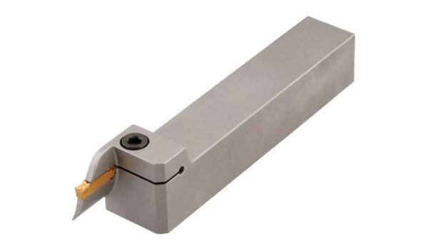
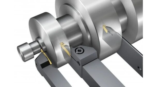
- Outer Diameter (OD): These are for cutting along the outside of the work piece. You will use them to machine keyways, O ring grooves or decorative features. Built for radial feeding and have good chip control, lathe groove tool designs ensure smooth surface finishes.
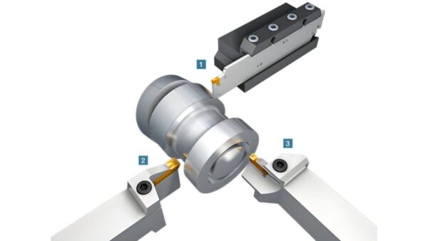
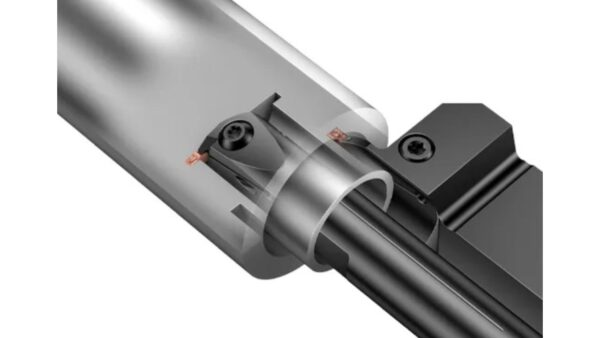
- Inner Diameter (ID): These tools are designed for internal cuts and allow you to get into bores or pipe interiors. Deep grooving operations require especially good rigidity and chip extraction from ID tools.
Insert Shapes and Toolholders
How stable and efficient your setup is depends on insert geometry and holder design.
- Insert Shapes: Depending on the groove profile, you can choose rectangular, round or custom shaped inserts. Straight grooves are most commonly encountered with rectangular inserts. Rounded grooving inserts help when forming contours.
- Fixed vs. Replaceable Inserts: The fixed tools are more rigid, but are more difficult to maintain. Replaceable inserts give you flexibility. In production, you can swap out worn edges quickly without having to change the whole tool.
- Quick-Change Tooling Systems: Quick change systems are helpful if you have a busy shop or you need to decrease setup time when using a tool. This will minimize downtime and ensure production processes are as efficient as possible.
Tool Design Parameters
Tool geometry is the last piece of the puzzle. These small details have a direct impact on the quality of the groove produced, tool life, and machining stability.
- Rake Angle: It affects how the chip flows. A rake angle that is greater than zero reduces cutting forces and makes cutting smoother. This is especially helpful for softer or ductile materials, particularly when using metal grooving operations.
- Clearance Angle: It prevents the tool from rubbing on the groove wall. Cleaner grooves are the result of proper clearance that reduces heat and wear, especially when working with a face grooving tool holder.
- Nose Radius: A larger nose radius produces a better surface finish but increases cutting force. However, a smaller radius provides more detail, but will wear faster. Decide based on your finish and tolerance requirement.
- Shank Size: This defines the tool’s stiffness. A thicker shank decreases vibration and improves accuracy. Always use shank size that matches your machine’s toolholder for maximum stability.
How to Perform Grooving with CNC Machines
Step 1: Design of the Groove in CAD.
Start with designing the groove using your favorite CAD software such as SolidWorks, AutoCAD or Fusion 360. You have to define the exact groove location, groove type, width, depth and tolerance. This stage will bring your final cut to the intended design and function. Always double check dimensions before moving forward, especially when preparing for 2 pass grooving operations.
Step 2 — File Conversion and CAM Programming
Once your CAD design is ready, then convert this into a machine readable format, for instance, STEP or IGES. Then, import it into CAM software such as Mastercam or Fusion 360 CAM. Here you’ll be creating the Gcode that is exactly what the CNC machine needs to know what to do. At this stage, you will specify the correct feed rate, spindle speed, and cutting depth for your lathe grooving tool setup
Step 3: CNC Machine Setup
Now, prepare your CNC machine. Use the appropriate grooving lathe tool for the material and groove size. You will want to securely install it and secure your workpiece as well. Set the Z zero point and offsets for the tool accurately. This ensures that your tool starts and finishes at the intended points.
Step 4: Execution of the Grooving Process
The CNC machine is used to execute the grooving process. Maintain the feed rate, spindle speed, and cut depth as close as possible. Use of coolants or lubricant limits heat and also helps get more tool life.
Step 5: Post-Process Inspection
Groove the part, then check the groove with calipers, micrometers or profile gauges. They should be checked for surface finish and dimensions. If necessary, do rework of the part, like deburring or polishing to meet the final quality standards.
Types of Grooving Methods
Face Grooving
Face grooving cuts along the face that is perpendicular to the workpiece axis. It is often used when machining cover plates, retaining rings or circular recesses. The lathe groove tool positioning and stable cutting conditions required are very precise.
Straight (Cylindrical) Grooving
This grooving tool lathe method has linear grooves that are parallel to the axis of rotation. This is very common in shaft manufacture where alignment and depth control are most critical. This is ideal when you need a consistent groove dimension along the cylindrical surface.
Contour Grooving
Deep grooving or Contour grooving can provide flexibility for complex parts. The path it follows is curved or non linear and requires an advanced CAM programming. This method will be used for intricate aerospace or automotive components where precision and design complexity meet.
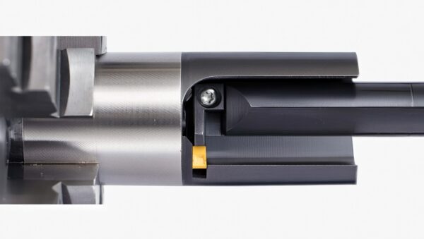
Internal Grooving
Internal grooving lathe tool operations lets you cut grooves on the inside of bores and cavities. There will be challenges like chip evacuation and limited access in bushings or small diameter inner rings.
External Grooving
This method will be used to cut grooves on the outside diameter. It can be used for key slots, O ring seats, or step cuts. There are single-cut, multiple-cut, or ramping strategies which you can use during groove machining.
Axial vs. Radial Grooving
Axial grooving feeds the tool along the axis, while radial grooving moves it perpendicular to the axis. Knowing both allows you to create the ideal tool path to not only enhance strength but precision using face grooving tool lathe setups.
Key Considerations When Choosing Grooving Tools
Groove Type and Dimensions
First, match the geometry to the width, depth and profile of the groove. Select a tool that is specifically designed for that cut, if the groove is narrow or deep. A wrong fit can vibrate or be dimensionally inaccurate. Be sure to always check that your part geometry matches the size of the insert shape and face grooving tool holder.
Workpiece Material
Be familiar with the material you’re dealing with. For grooving metal such as stainless steel or titanium you need more wear resistant tools – harder, carbide or coated inserts are best. For plastics and composites, choose tools with sharp edges to prevent tearing or melting. You must match the tool hardness with the material toughness.
Machine Capability
See if your CNC machine will be able to handle the 2 pass grooving load. Check toolholder size, turret capacity and spindle power. If your spindle is not a strong one or if your turret is not stable, your results will never be consistent. Check that your machine’s settings fit with what your groove requires.
Cutting Conditions
Change speed and feed according to material/tool combination. Coolant can be used to help control heat during long cut. Verify tool compatibility for dry cutting to prevent premature tool wear. These settings require fine tuning to get smooth, accurate grooves.
Chip Evacuation and Surface Finish
A good chip removal will result in a better finish and tool life. Use tools that provide chip clearing access. Watch tolerances and finish, especially sealing grooves and grooving line accuracy
Tool Life and Reusability
You have to choose between insert based tools and regrindable HSS. HSS tools are more re-usable for small runs and inserts are fast to replace in high volume setups.
Common CNC Grooving Problems and Solutions
Poor Surface Finish
Incorrect speeds or dull tool often causes a poor surface finish. To address this issue, you should optimize your cutting speed and apply face grooving tool to minimize friction. In addition, coated tools have better wear resistance and better surface quality.
Tool Breakage
Sometimes the wrong tool material leads to tool breakage, or ineffective cooling causes tool breakage. To avoid this, apply proper coolant, reduce the depth of cut and use stronger inserts suited for the material being machined.
Inaccurate Dimensions
The most frequent origin of inaccurate dimensions is an incorrect calibration or unstable fixturing. To solve this, recalibrate the machine and improve fixturing stability for accurate cuts with correct dimensions.
Tool Vibration and Chatter
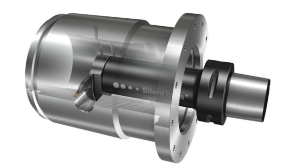
Overhang or an unstable tool holder gives rise to tool vibration and chatter. Shorter tools and anti vibration holders help you combat this problem. They help maintain tool stability and help to suppress vibration during thegrooving process.
Chip Control Issues
Chip control issues could occur if proper chip breakers were not used or if the wrong cutting angles were used. For the chips to be managed effectively and for the cutting to be smooth, use of tools with built in chip breakers or coolant jets will be required.
Excessive Tool Wear
Hard materials or the wrong tool coating may cause excessive tool wear. Appropriate coatings can be used to extend tool life and rotate the insert edges regularly to keep the edges sharp to prevent premature wear.
Applications of CNC Grooving in Industry
Hydraulics and Pneumatics
To manufacture precise grooves for O rings and sealing rings in hydraulics and pneumatics, advanced machining is required. These grooves are used to help keep a seal in valves and cylinders and prevent leaks. CNC grooving can be relied on to meet the tight tolerance requirements.
Aerospace Components
In pressure seals and fittings, a very high level of tolerancing is required for aerospace components, and CNC grooving is an important step in the process. This industry requires an extreme precision. Using CNC machines will enable the grooves to fit well, increasing performance and safety of aerospace parts.
Medical Devices
CNC grooves are precise, and are necessary for medical devices. The industry use grooving for implants such as joints and screws and surgical instruments to provide a perfect fit. This precise grooving also helps to solve application problems such as movement or misalignment in sensitive medical applications.
Automotive Industry
Automotive industries are now using CNC grooving to form grooves on the very critical components like drive shafts, pistons and the gear assemblies. These parts feature grooves that improve performance and allow them to operate in high stress environments.
Electronics Manufacturing
Micro grooving is commonly used in electronics manufacturing, especially in connectors and enclosures. The tiny, precise grooves produced by advanced machining play an important role in the effective working of electronic components.
Oil & Gas Sector
CNC grooving is required in oil and gas industry for making high pressure seals, flange connections and pipe grooves. This grooving helps to seal the pipes very well under extreme pressures thereby improving safety as well as operational efficiency.
Conclusion
Finally, CNC grooving is a precise, versatile process utilized in such industries as aerospace, automotive, and more. High quality results can only be achieved if the right cutoff tools, methods, and machine setup are chosen. Selecting proper tools and machine calibration properly is important to the accuracy and durability of grooved components. Troubleshooting common problems such as tool wear or poor surface finishes will greatly increase productivity and product quality. To do so, you can partner with skilled CNC experts who can help you optimize your grooving processes to improve outcomes and lower your manufacturing operation costs.